THE NOT SCHMITT TRIGGER (INVERTER)
We can try and prove the function of The Not Schmitt Gate as Clock Generator with following this Circuit Diagram in ELECTRONIC WORK BENCH
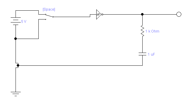
And these are several information about THE NOT SCHMITT TRIGGER


Schmitt Trigger Characteristic:
The output is HIGH until the input rises to 66% of rail voltage.
The output goes LOW when the input goes above 66%.
The output remains HIGH until the input fall to 33%.
The output goes LOW when the input goes above 66%.
The output remains HIGH until the input fall to 33%.
A Schmitt Trigger gate can be wired as an oscillator, delay, inverter (and other functions, depending on the surrounding components).
Fig: 5 shows the Schmitt Trigger wired as an oscillator, delay and inverter:
Fig: 5 shows the Schmitt Trigger wired as an oscillator, delay and inverter:
Each of the 6 gates in the 74c14 can be used to create a separate "building block" and this gives the chip a wide range of capabilities.
Schmitt Inverter Waveform Generator

This simple waveform generator circuit consists of a single TTL 74LS14 Schmitt inverter logic gate
with a capacitor, C connected between its input terminal and ground, ( 0v ) and the positive feedback required for the circuit to oscillate being provided by the feedback resistor, R.
with a capacitor, C connected between its input terminal and ground, ( 0v ) and the positive feedback required for the circuit to oscillate being provided by the feedback resistor, R.
So how does it work?. Assume that the charge across the capacitors plates is below the Schmitt’s lower threshold level of 0.8 volt (Datasheet value). This therefore makes the input to the inverter at a logic “0” level resulting in a logic “1” output level (inverter principals).
One side of the resistor R is now connected to the logic “1” level ( +5V ) output while the other side of the resistor is connected to the capacitor, C which is at a logic “0” level (0.8v or below). The capacitor now starts to charge up in a positive direction through the resistor at a rate determined by the RCtime constant of the combination.
When the charge across the capacitor reaches the 1.6 volt upper threshold level of the Schmitt trigger (datasheet value) the output from the Schmitt inverter rapidly changes from a logic level “1” to a logic level “0” state and the current flowing through the resistor changes direction.
This change now causes the capacitor that was originally charging up through the resistor, R to begin to discharge itself back through the same resistor until the charge across the capacitors plates reaches the lower threshold level of 0.8 volts and the inverters output switches state again with the cycle repeating itself over and over again as long as the supply voltage is present.
So the capacitor, C is constantly charging and discharging itself during each cycle between the inputs upper and lower threshold levels of the Schmitt inverter producing a logic level “1” or a logic level “0” at the inverters output. However, the output waveform is not symmetrical producing a duty cycle of about 33% or 1/3 as the mark-to-space ratio between “HIGH” and “LOW” is 1:2 respectively due to the input gate characteristics of the TTL inverter.
The value of the feedback resistor, ( R ) MUST also be kept low to below 1kΩ for the circuit to oscillate correctly, 220R to 470R is good, and by varying the value of the capacitor, C to vary the frequency. Also at high frequency levels the output waveform changes shape from a square shaped waveform to a trapezoidal shaped waveform as the input characteristics of the TTL gate are affected by the rapid charging and discharging of the capacitor. The frequency of oscillation for Schmitt Waveform Generators is therefore given as:
Schmitt Waveform Frequency

With a resistor value between: 100R to 1kΩ, and a capacitor value of between: 1nF to 1000uF. This would give a frequency range of between 1Hz to 1MHz, (high frequencies produce waveform distortion).
Generally, standard TTL logic gates do not work too well as waveform generators due to their average input and output characteristics, distortion of the output waveform and low value of feedback resistor required, resulting in a large high value capacitor for low frequency operation. Also TTL oscillators may not oscillate if the value of the feedback capacitor is too small. However, we can also make Astable Multivibrators using better CMOS logic technology that operate from a 3V to 15V supply such as the CMOS 40106B Schmitt Inverter.
The CMOS 40106 is a single input inverter with the same Schmitt-trigger action as the TTL 74LS14 but with very good noise immunity, high bandwidth, high gain and excellent input/output characteristics to produce a more “squarer” output waveform as shown below.
CMOS Schmitt Waveform Generator

The Schmitt waveform generators circuit for the CMOS 40106 is basically the same as that for the previous TTL 74LS14 inverter, except for the addition of the 10kΩ resistor which is used to prevent the capacitor from damaging the sensitive MOSFET input transistors as it discharges rapidly at higher frequencies.
The mark-space ratio is more evenly matched at about 1:1 with the feedback resistor value increased to below 100kΩ resulting in a smaller and cheaper timing capacitor, C. The frequency of oscillation is given the same: ( 1/1.2RC ), with a resistor value between: 1kΩ and 100kΩ, and a capacitor value of between: 1pF to 100uF. This would give a frequency range of between 0.1Hz to 100kHz.
Schmitt Inverter Waveform Generators can also be made from a variety of different logic gates connected to form an inverter circuit. The basic Schmitt astable multivibrator circuit can be easily modified with some additional components to produce different outputs or frequencies. For example, two inverse waveforms or multiple frequencies and by changing the fixed feedback resistor to a potentiometer the output frequency can be varied as shown below.
Clock Waveform Generators

In the first circuit above, an additional Schmitt Inverter has been added to the output of the Schmitt waveform generator to produce a second waveform that is the inverse or mirror image of the first producing two complementary output waveforms, so when one output is “HIGH” the other is “LOW”. This second Schmitt inverter also improves the shape of the inverse output waveform but adds a small “gate delay” to it so it is not exactly in synch with the first.
Also, the output frequency of the oscillator circuit can be varied by changing the fixed resistor, R into a potentiometer but a smaller feedback resistor is still required to prevent the potentiometer from shorting out the inverter when its at its minimum value, 0Ω’s.

We can also use the two complementary outputs, Q and Q of the first circuit to alternatively flash two sets of lights or LED’s by connecting their outputs directly to the bases of two switching transistors as shown.
In this way one or several LED’s connected together in series with the collector of the switching transistors resulting in alternating flashes of each set of LED’s as each transistor is switched “ON” in turn.
Also when using this type of circuit, remember to calculate a suitable series resistor, R to limit the LED current to below 20mA (red Led’s) for the voltage you are using.
In order to generate a very low frequency output of a few Hertz to flash the LED’s, Schmitt waveform generators use high value timing capacitors which themselves can be physically large and expensive.
One alternative solution is too use a smaller value capacitor to generate a much higher frequency, say 1kHz or 10kHz, and then divide this main clock frequency down into individual smaller ones until the required low frequency value is achieved, and the second circuit above does just that.
The lower circuit above shows the oscillator being used to drive the clock input of a ripple counter. Ripple counters are basically a number of divide-by-2, D-type flip-flops cascaded together to form a single divide-by-N counter, where N is equal to the counters bit-count such as the CMOS 4024 7-bit Ripple Counter or the CMOS 4040 12-bit Ripple Counter.
The fixed clock frequency produce by the Schmitt astable clock pulse circuit is divided into a number of different sub-frequencies such as, ƒ÷2, ƒ÷4, ƒ÷8, ƒ÷256, etc, up to the maximum “Divide-by-n” value of the ripple counter being used. This process of using either “Flip-flops”, “Binary Counters” or “Ripple Counters” to divide a main fixed clock frequency into different sub-frequencies is known asFrequency Division and we can use it to obtain a number of frequency values from a single waveform generator.


Comments
Post a Comment